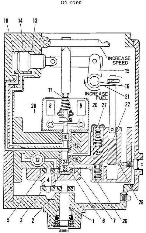
A schematic diagram of an isochronous hydraulic governor is shown in the illustration. When the load is removed the speed increases, and the __________. Illustration MO-0100
Official USCG Answer & Rule Citation
Correct Answer: Option C — pilot valve (piece 10) moves upward
When an isochronous hydraulic governor experiences a load drop and subsequent speed increase, flyweights move outward, shifting the pilot valve (piece 10) upward. This action uncovers control ports to redirect oil flow and reposition the power piston, reducing fuel delivery.
100% Free & Open Access — No daily limits, paywalls, or gated answers on BrightMariner.