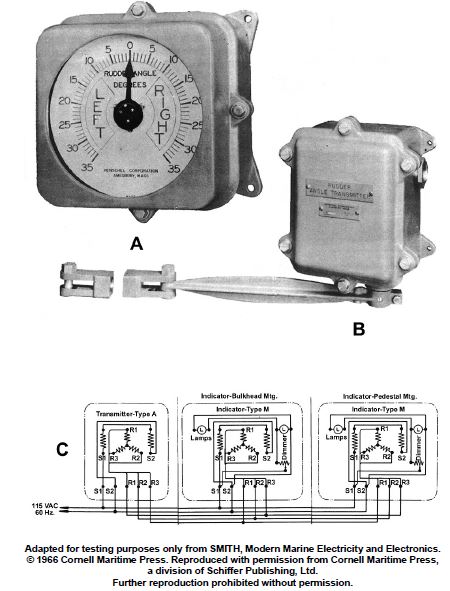
In actual applications, electrical connections associated with 'R1, R2 and R3' of the transmitter to 'R1, R2, and R3' of the indicators shown in figure "C" of the illustration are made by what means? EL-0092
Official USCG Answer & Rule Citation
Correct Answer: Option A — slip rings and brushes
Synchro transmitter and receiver rotor connections (R1, R2, R3) rely on internal slip rings and brushes to maintain continuous electrical continuity as the shafts rotate through various angular positions.
100% Free & Open Access — No daily limits, paywalls, or gated answers on BrightMariner.