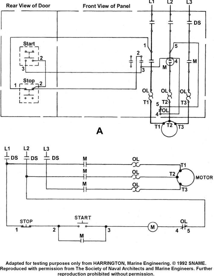
What statement is true concerning the electrical diagrams for the motor controller shown in the illustration? Illustration EL-0007
Official USCG Answer & Rule Citation
Correct Answer: Option B — Figure "A" is a wiring diagram and figure "B" is a ladder or line diagram (schematic).
Figure A provides a physical wiring diagram showing actual component placement and terminal connections, whereas Figure B is a ladder or schematic diagram designed for logical troubleshooting. Per IEEE 45 guidelines, schematics use horizontal rungs to represent control logic without regard to physical device locations.
100% Free & Open Access — No daily limits, paywalls, or gated answers on BrightMariner.