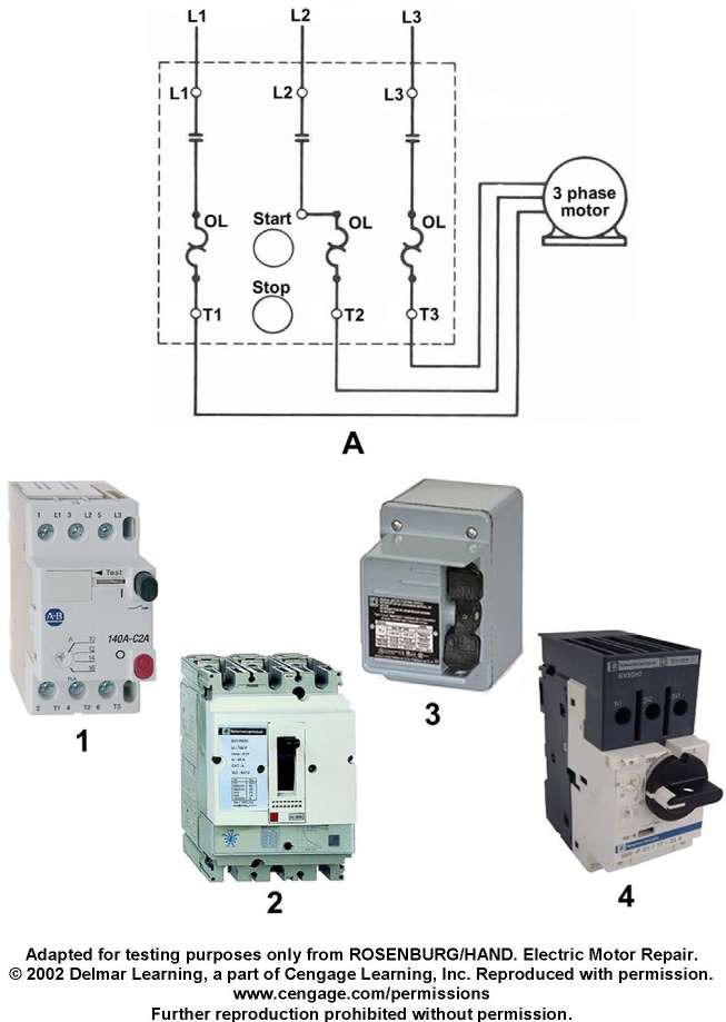
Which of the following illustrated manual motor starters represents the wiring diagram illustrated in figure "A"? Illustration EL-0023
Official USCG Answer & Rule Citation
Correct Answer: Option B — 1
Manual motor starter wiring diagram configurations dictate specific terminal connections for thermal overload blocks and contact blocks. Figure 1 accurately corresponds to the schematic arrangement shown in figure A, matching line-side power distribution paths and motor terminal leads per marine engineering conventions.
100% Free & Open Access — No daily limits, paywalls, or gated answers on BrightMariner.